4-Way GPS Splitter GS14

√ Full GNSS band:GPS/GLONASS/Beidou/Galileo/IRNSS/QZSS/SBAS/NAVIC/OmniStar; √ Frequency Range:1150~1650MHz; √ Gain(amplified):0dB ~ 21dB(be specified); √ Passive: -7.5dB (be specified); √ Pass DC In & J1 and Block DC J2,J3,J4 √ High Isolation: >30dB;

Classification:

Product

GPS and GNSS Splitters


+
  • 553.jpg
  • GS14-1.png
  • DESCRIPTION
  • Videos
  • Download
  • BUY NOW
  • 【Description】

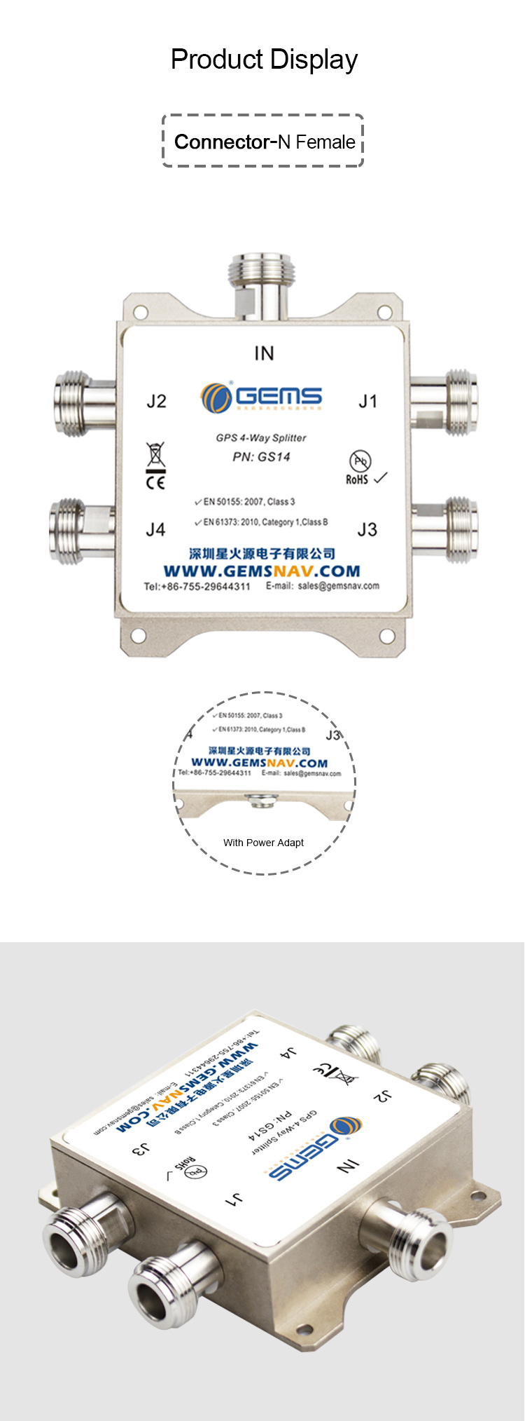
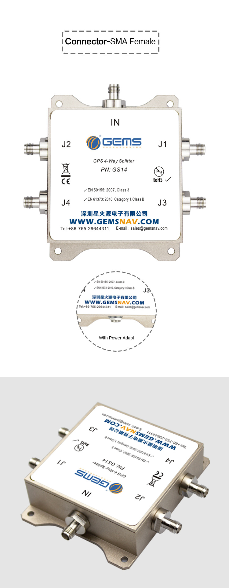
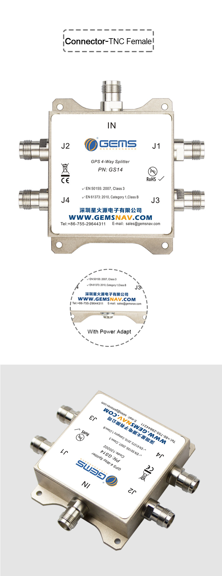
    The GS14 GPS Splitter is a one‐input, four‐output GNSS splitter device. This product typically finds application where an input from an active GPS roof antenna is split、 evenly between four receiving GPS receivers.

    The GS14 can be configured to pass DC from an RF output (J1) to the antenna input port in order to power an active GPS antenna on that port. The second, third and fourth RF outputs (J2,J3, & J4) would feature a 200 Ohm DC load to simulate an antenna DC current draw for any receiver connected to those ports.

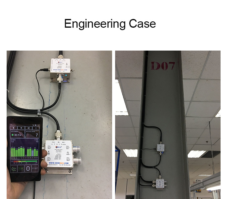
    The most common application is the input from an active GPS/GNSS roof antenna or GPS simulator is equally split to four receivingg GPS units. The GS14 will support long-lasting, trouble free deployment in a small cell wireless and/or CORS center stations. The device makes it possible to use a single GPS/GNSS referencing antenna for synchronization systems, increasing capacity without increasing GPS/GNSS antennas or cabling requirements.

    【Technical Parameters】

    Design For Wireless Infrastructure Applications

    Gain 0dB, 21dB And Passive Version Available

    High lsolations > 30dB

    Excellent Gain Flatness Gain L1-L2 < 2dB

    ROHS/WEEE Compliant

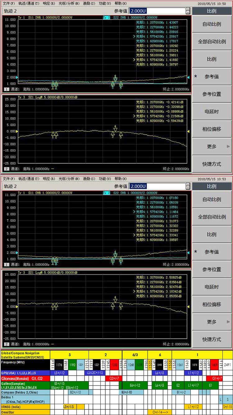
    Response For Full GNSS band:GPS/GLONASS/Beidou/Galileo/RNSS/QZSS/SBAS/NAVIC:

    High Isolations > 30dB

    Specifications

    Parameter

    Conditions

    Min

    Typ

    Max

    Units

    Freq. Range

    Ant – Any Port

    1150


    1650

    MHz

    In &Out Imped.

    In, all output ports


    50


    Ω

    Gain

    0dB

    In- Output ports, ,Unused Ports - 50Ω

    -1

    0

    1

    dB

    Amplified(Normal)

    19.5

    21

    22.5

    Loss, Passive

    In- Output ports, ,Unused Ports - 50Ω

    6.5

    7.5

    8.5

    dB

    Input SWR


    2.0:1

    -

    Output SWR


    2.0:1

    -

    Nois Figure- Amplified


    1.5

    dB

    Gain Flatness

    Amplified


    1.5

    dB

    Passive


    1

    dB

    Amp. Balance


    0.5

    dB

    Phase Balance


    1.0

    deg

    Group Delay Flatness


    1

    ns

    Isolation

    (Passive)

    Unused Ports - 50Ω

    7


    dB

    0∽10dB

    Unused Ports - 50Ω

    29


    10∽21dB

    Unused Ports - 50Ω

    24


    DC IN

    DC Block, All ports with a 200Ω Load

    3.3

    5

    16

    VDC

    PASS DC, Amplified

    3.3

    5

    16

    PASS DC, Passive

    3.3

    3

    16

    AC IN

    Adapter  Load


    12


    Device Current


    16

    mA

    Current

    Pass DC, No Powered configuration, DC input on J1


    250

    mA

    Operating Temperature


    -40


    85

    Max RF Input

    -Amplified

    -Passive

    Max RF input without damage


    0

    dBm


    30

    RF Characterization Parameter Table

    Frequency(MHZ)

    Gain(dB)

    Isolation(dB)

    0

    21

    Total LOSS

    0

    21

    Total LOSS


    S-1

    S-2

    S-3

    S-4

    S-1

    S-2

    S-3

    S-4

    S-1

    S-2

    S-3

    S-4

    1-2

    2-3

    1-2

    3-4

    1-2

    3-4

    1150

    0.0

    0.0

    -0.1

    0.0

    20.7

    20.6

    20.8

    20.4

    -7.4

    -7.3

    -7.5

    -7.6

    29

    29

    25

    24

    7

    7

    1176

    0.1

    0.1

    -0.1

    0.1

    20.8

    20.7

    20.9

    20.5

    -7.4

    -7.4

    -7.5

    -7.6

    29

    29

    25

    25

    7

    7

    1207

    0.5

    0.5

    0.0

    0.4

    21.5

    21.6

    21.2

    21.2

    -7.3

    -7.2

    -7.4

    -7.4

    31

    31

    27

    27

    7

    7

    1227

    0.6

    0.4

    0.2

    0.4

    21.2

    21.5

    21.3

    21.4

    -7.2

    -7.1

    -7.4

    -7.4

    31

    31

    28

    27

    7

    7

    1268

    0.4

    0.3

    0.2

    0.3

    21.2

    21.4

    21.2

    21.3

    -7.3

    -7.2

    -7.3

    -7.3

    32

    40

    28

    28

    7

    7

    1545

    0.4

    0.5

    0.2

    0.4

    21.4

    21.5

    21.5

    21.3

    -7.5

    -7.5

    -7.6

    -7.6

    37

    40

    26

    23

    9

    9

    1561

    0.3

    0.5

    0.2

    0.4

    21.5

    21.6

    21.5

    21.3

    -7.5

    -7.5

    -7.7

    -7.7

    37

    40

    26

    23

    9

    9

    1575

    0.2

    0.5

    0.1

    0.2

    21.2

    21.2

    21.2

    21.1

    -7.6

    -7.5

    -7.7

    -7.8

    39

    40

    26

    23

    9

    9

    1609

    0.1

    0.2

    -0.2

    -0.2

    20.3

    20.4

    20.2

    20.4

    -7.9

    -7.9

    -8.1

    -8.1

    41

    41

    26

    24

    10

    10

    1650

    -0.4

    -0.2

    -0.6

    -0.3

    18.9

    19.1

    18.9

    18.8

    -7.9

    -7.8

    -8.1

    -8.0

    45

    45

    29

    27

    10

    10


    Frequency(MHZ)

    VSWR

    Noise(dB)

    0

    21

    Total LOSS

    0

    5

    21


    S

    1

    2

    3

    4

    S

    1

    2

    3

    4

    S

    1

    2

    3

    4

    S

    S

    S

    1150

    1.6

    1.4

    1.3

    1.4

    1.4

    1.5

    1.4

    1.3

    1.4

    1.4

    1.6

    1.5

    1.4

    1.5

    1.5

    3.8

    1.8

    1.0

    1176

    1.5

    1.3

    1.3

    1.4

    1.3

    1.4

    1.4

    1.3

    1.4

    1.4

    1.6

    1.5

    1.4

    1.4

    1.4

    3.3

    1.8

    1.0

    1207

    1.5

    1.3

    1.3

    1.4

    1.3

    1.4

    1.4

    1.2

    1.4

    1.4

    1.5

    1.4

    1.3

    1.4

    1.4

    3.4

    1.8

    1.0

    1227

    1.4

    1.3

    1.3

    1.4

    1.3

    1.4

    1.3

    1.2

    1.4

    1.4

    1.5

    1.4

    1.3

    1.4

    1.4

    3.3

    1.7

    1.1

    1268

    1.4

    1.3

    1.3

    1.3

    1.3

    1.4

    1.3

    1.2

    1.3

    1.3

    1.5

    1.3

    1.3

    1.4

    1.4

    3.3

    1.6

    1.1

    1545

    1.2

    1.2

    1.2

    1.2

    1.2

    1.4

    1.1

    1.2

    1.1

    1.2

    1.2

    1.5

    1.4

    1.5

    1.5

    3.4

    1.8

    1.2

    1561

    1.2

    1.2

    1.2

    1.2

    1.2

    1.4

    1.1

    1.2

    1.1

    1.2

    1.2

    1.5

    1.4

    1.5

    1.5

    3.5

    1.9

    1.2

    1575

    1.2

    1.2

    1.2

    1.2

    1.2

    1.4

    1.1

    1.2

    1.1

    1.2

    1.2

    1.5

    1.4

    1.5

    1.5

    3.7

    2.0

    1.3

    1609

    1.2

    1.2

    1.2

    1.2

    1.2

    1.3

    1.1

    1.2

    1.1

    1.2

    1.2

    1.5

    1.5

    1.5

    1.5

    3.8

    2.1

    1.3

    1650

    1.3

    1.2

    1.2

    1.2

    1.2

    1.3

    1.1

    1.2

    1.2

    1.2

    1.2

    1.5

    1.5

    .5

    1.5

    4.0

    2.2

    1.4


    picpicpicpicpicpipipi

Keyword:

GPS splitter

GNSS Splitters

Professional consultant

We provide you with 1 on 1 exclusive services

contact

Related products

2-Way GPS Splitter MGS12

√ Full GNSS band Supported √ Passed The 96-Hour Salt Spray Test(Optional) √ MGS12 J1 output port energized √ Frequency Range:1150~1650MHz; √ Gain(amplified):0dB ~ 21dB(be specified) √ Passive: -4.5dB (be specified); √ High lsolation:>28dB. √ Low Noise Figure: <1.5dB

Military Qualified GNSS Splitter GS112-55

√ Military grade:-55°~85° √ Gain:55dB(0-55dB Optional); √ X0 port pass-through antenna:-5dB~0dB; √ Operating frequency range:1150MHz ~1650MHz; √ RF connector:SMA Female with self-locking(Optional); √ Power connector: Aviation connectors; √ Power supply mode: √ 220VAC to 12VDC power adapter power supply;(Standard) √ The antenna feed port is powered by a receiver of X0, Voltage:5V DC √ Number of output ports:12 with gain, 1 pass-through without gain

2-Way GPS Splitter GS12

√ Full GNSS band:GPS/GLONASS/Beidou/Galileo/IRNSS/QZSS/SBAS/NAVIC; √ Frequency Range:1164~1616MHz; √ Gain(amplified):0dB ~ 24dB(be specified); √ Passive: -4.5dB (be specified); √ Pass DC In & J1 and Block DC J2 √ High Isolation: >30dB; √ Low Noise Figure: <2.5dB

2-Way GPS Splitter MGS12i

√ Pass DC from J1 and J2 to In Port; √ Full GNSS band Supported √ Passed The 96-Hour Salt Spray Test(Optional) √ Frequency Range:1150~1650MHz; √ Gain(amplified):0dB ~ 21dB(be specified) √ Passive: -4.5dB (be specified); √ High lsolation:>28dB. √ Low Noise Figure: <1.5dB

Online Message

Submit Message